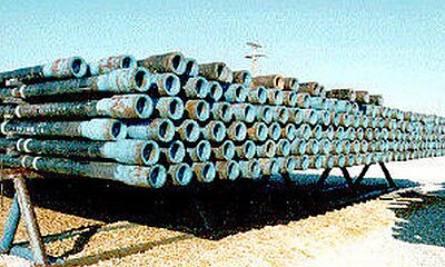
133:. The tube is held stationary while the tool joint is revolved at high RPMs. The tool joint is then firmly pressed onto the upset end of the tube while the tool joint is rotating. The heat and force during this interaction weld the two together. Once the "ram horns" or excess material is removed, the weld line can only be seen under a microscope. Inertia friction welding is the traditional proven method. Direct drive friction welding is controlled and monitored up to 1,000 times a second, resulting in a fine quality weld that does not necessarily need a full heat treat quench and temper regime.
99:(BHA), which is the tubular portion closest to the bit. The BHA will be made of thicker walled heavy weight drill pipe (HWDP) and drill collars, which have a larger outside diameter and provide weight to the drill bit and stiffness to the drilling assembly. Other BHA components can include a mud motor, measurement while drilling (MWD) apparatus, stabilizers, and various specialty downhole tools. The drill stem includes the entire drill string, plus the
119:
end may be externally upset (EU), internally upset (IU), or internally and externally upset (IEU). Standard max upset dimensions are specified in API 5DP, but the exact dimensions of the upset are proprietary to the manufacturer. After upsetting, the tube then goes through a heat treating process. Drill pipe steel is commonly quenched and tempered to achieve high yield strengths (135 ksi is a common tube yield strength).
72:, and also must be able to resist pressure differentials between inside and outside (or vice versa), and have sufficient strength to suspend the total weight of deeper components. For deep wells this requires tempered steel tubes that are expensive, and owners spend considerable efforts to reuse them after finishing a well.
123:
They generally are stiffer than the tube, increasing the likelihood of fatigue failure at the junction. The lower SMYS on the connection increases the fatigue resistance. Higher strength steels are typically harder and more brittle, making them more susceptible to cracking and subsequent stress crack propagation.
118:
Modern drill pipe is made from the welding of at least three separate pieces: box tool joint, pin tool joint, and the tube. The green tubes are received by the drill pipe manufacturer from the steel mill. The ends of the tubes are then upset to increase the cross-sectional area of the ends. The tube
91:
of the drill stem during future wellboring. Drill pipe is most often considered premium class, which is 80% remaining body wall (RBW). After inspection determines that the RBW is below 80%, the pipe is considered to be Class 2 or "yellow band" pipe. Eventually the drill pipe will be graded as scrap
122:
The tool joints (connectors) are also received by the manufacturer as green tubes. After a quench and temper heat treat, the tool joints are cut into box (female) and pin (male) threads. Tool joints are commonly 120 ksi
Specified Minimum Yield Strength (SMYS), rather than the 135 ksi of the tube.
35:
28:
60:. It comes in a variety of sizes, strengths, and wall thicknesses, but is typically 27 to 32 feet in length (Range 2). Longer lengths, up to 45 feet, exist (Range 3).
68:
Drill stems must be designed to transfer drilling torque for combined lengths that often exceed several miles down into the
155:
167:
147:
95:
Drill pipe is a portion of the overall drill string. The drill string consists of both drill pipe and the
17:
107:
49:
183:
96:
8:
84:
76:
57:
151:
130:
69:
188:
45:
53:
177:
127:
100:
80:
88:
164:
Recommended
Practice for Drill Stem Design and Operating Limits
103:
that imparts rotation and torque to the drill pipe at the top.
34:
83:
are used at inspection sites to identify defects from metal
27:
56:
to be pumped down the hole through the bit and back up the
126:
Tubes and tool joints are welded using rotary inertia or
75:
A used drill stem is inspected on site, or off location.
44:, is hollow, thin-walled, steel or aluminium alloy
175:
141:
113:
79:and modified instruments similar to the
14:
176:
144:Fundamentals of the Petroleum Industry
24:
33:
26:
25:
200:
110:for a diagram of a drilling rig.
13:
1:
136:
63:
168:American Petroleum Institute
148:University of Oklahoma Press
142:Anderson, Robert O. (1984).
92:and marked with a red band.
7:
10:
205:
52:. It is hollow to allow
108:Drilling rig (petroleum)
87:, in order to preclude
38:
31:
114:Manufacturing Process
37:
30:
166:. Norman, Oklahoma:
146:. Norman, Oklahoma:
97:bottom hole assembly
77:Ultrasonic testing
39:
32:
16:(Redirected from
196:
171:
161:
131:friction welding
48:that is used on
21:
204:
203:
199:
198:
197:
195:
194:
193:
174:
173:
162:
158:
139:
116:
66:
23:
22:
15:
12:
11:
5:
202:
192:
191:
186:
184:Drilling fluid
156:
138:
135:
115:
112:
65:
62:
54:drilling fluid
9:
6:
4:
3:
2:
201:
190:
187:
185:
182:
181:
179:
172:
169:
165:
159:
157:0-585-19475-0
153:
149:
145:
134:
132:
129:
124:
120:
111:
109:
104:
102:
98:
93:
90:
86:
82:
78:
73:
71:
70:Earth's crust
61:
59:
55:
51:
50:drilling rigs
47:
43:
36:
29:
19:
163:
143:
140:
128:direct drive
125:
121:
117:
105:
94:
74:
67:
41:
40:
81:spherometer
178:Categories
137:References
64:Background
42:Drill pipe
18:Drillpipe
89:fracture
170:. 1998.
85:fatigue
58:annulus
189:Piping
154:
46:piping
101:kelly
152:ISBN
106:See
180::
150:.
160:.
20:)
Text is available under the Creative Commons Attribution-ShareAlike License. Additional terms may apply.

